Search

Formwork beams

Product range
& data

Here you can find all product infos on the formwork beams PF20 range of products.plus and PF20 by Pfeifer.

Product features

Overview

PF20plusEnd cap up to 9 m possible
PF20Curvature with sealing up to 9 m possible – over 9 m only cut straight and sealed
Weightapprox. 4.5 kg/lfm
Bar thickness27 mm
Lengths190, 245, 265, 290, 330, 360, 390, 450, 490, 590 cm
Special lengths up to 11.90 m
Package units100 pieces per package
Package dimensions
(w x h)
110 x 110 (100 pieces; without underlay)
Max. number of stacks on top of each other2 (100 pieces)
Wood moisture12 % +/– 2 % upon delivery
Dimensional tolerancesHeight H = 200+/– 2 mm;
Length tolerance: specified length +/–10 mm

Permissible loads for full-wall beams according to EN 13377

Transverse force QQ = 11 kN
Bearing force AA = 22 kN
Bending moment MM = 5 kNm
Bending stiffnessEI = 450 kNm²
The strength of the chords is sorted by machine

Characteristic limit values according to EN 13377

Transverse forceVk = 23,9 kN
Bearing resistanceRb,k = 47,8 kN
Bending momentMk = 10,9 kNm
Bending stiffnessEI = 450 kNm²

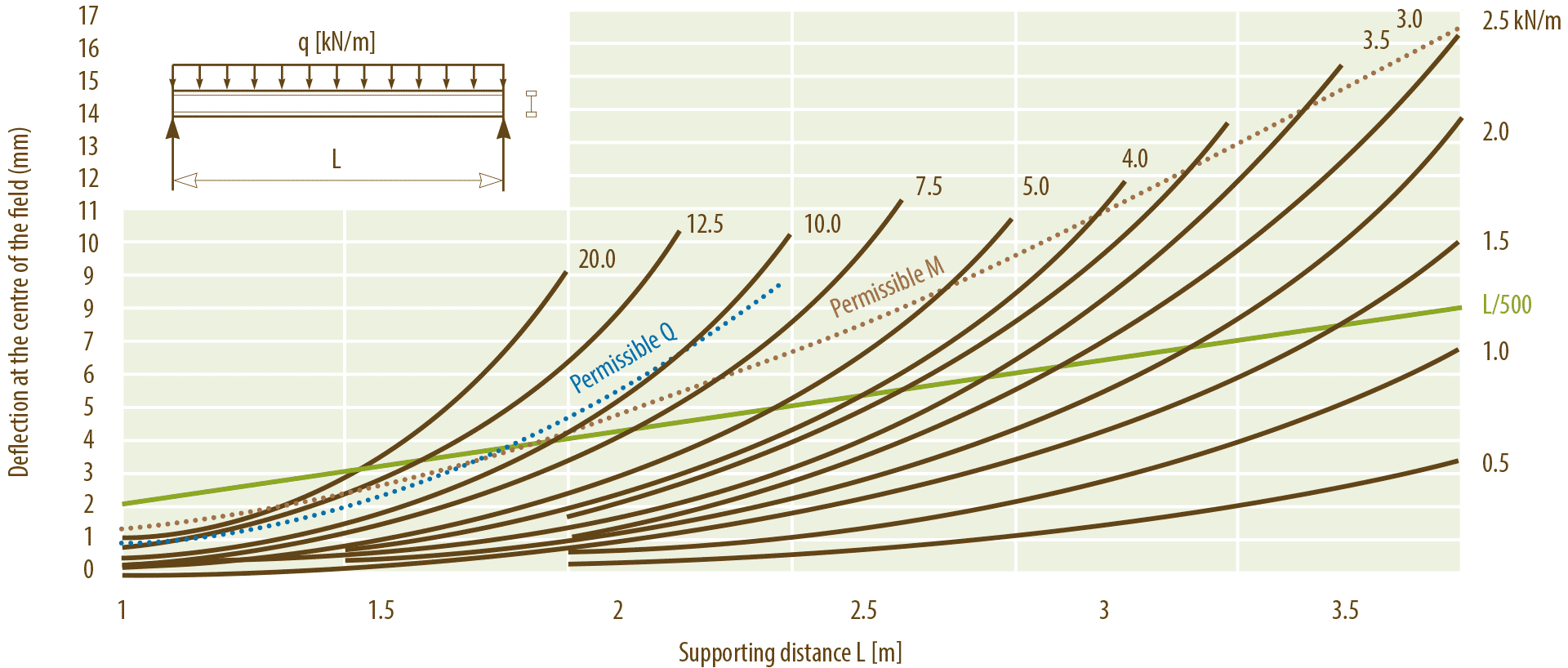
Deflection of the formwork beam

Pfeifer Schalungsträger Durchbiegungstabelle

Measurement table

  Table 1Table 2
  Cross beam distance (m)Yoke beam distance (m)
  0,500,630,670,751,001,251,501,752,002,252,503,003,50
Ceiling thickness in cmTotal load kN/m²Allowed span width for cross beams (m)Allowed span width for yoke beams in (m) = max. Distance of ceiling supports
104,403,633,373,293,172,882,672,462,282,132,011,911,671,43
124,923,433,193,123,002,722,532,332,162,021,901,791,491,28
145,443,273,042,972,862,602,412,412,051,921,801,621,351,16
165,963,142,922,852,742,492,312,121,901,831,641,481,231,05
186,483,032,812,752,652,402,222,031,881,701,511,361,130,97
207,002,932,722,662,562,322,141,951,801,571,401,201,050,90
227,522,842,642,582,482,262,061,881,671,461,301,170,980,84
248,042,762,572,512,422,192,001,821,561,371,221,090,910,78
268,562,702,502,452,352,141,931,711,471,291,141,030,860,73
289,082,632,442,392,302,091,881,621,381,211,080,970,810,69
309,662,572,392,342,252,031,821,521,301,141,010,910,760,65
3511,222,452,272,232,141,891,571,311,120,980,870,780,650,56
4012,782,352,182,132,041,721,381,150,980,860,770,690,570,49
4514,342,262,102,04 1,531,231,020,880,770,680,610,510,44
5015,902,182,011,94 1,381,110,920,790,690,610,550,460,40
Case example:
  • given: Ceiling thickness (18 cm) + Cross beam distance (75 cm)
  • searched: Yoke beam distance + support distance
  • 1 Ceiling thickness: 18 cm
  • 2 Cross beam distance: 75 cm
  • 3 Allowed yoke beam distance according to table 1 = 2.65 m.
  • 4 equals or choose the next lower yoke beam distance in the table 2: 2.50 m
  • 5 in table 2 column 2.5 according to ceiling thickness (18 cm) read the allowed support distance: 1.36 m
  • 6 Attention: Supports have to be controlled in terms of corresponding load capacity!

    The deflection of beams is limited to L/500.
    Traffic load 1,5 kN/m² or 20% of fresh concrete weight.